Energieopslagsysteem | Samenstelling en ontwerp van een geïntegreerd inverter-boost-magazijn
Aug 30, 2024
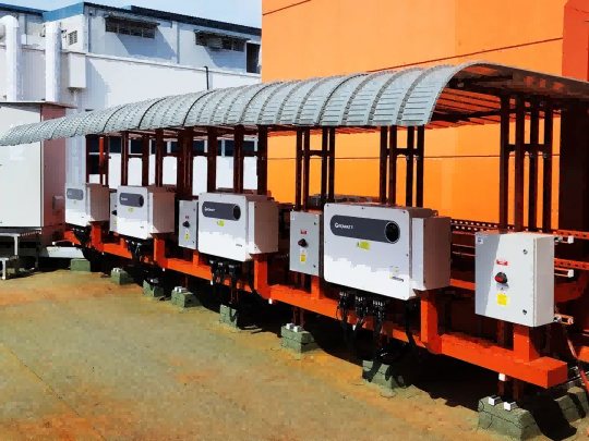
VoorwoordAls belangrijke uitrusting op het gebied van moderne energieconversie en -transmissie zijn het zorgvuldige ontwerp en de redelijke samenstelling van de geïntegreerde silo met inverter-boost de sleutel tot het bereiken van een efficiënte en stabiele werking.De omvormer-boost geïntegreerde cabine integreert, zoals de naam al doet vermoeden, de twee belangrijkste functies van PCS en boost in een compacte en efficiënte cabine. Dit geïntegreerde ontwerp brengt veel belangrijke voordelen met zich mee. Het volgende neemt een geïntegreerde silo van 2 MW met inverterboost als voorbeeld om de interne samenstelling en het ontwerp te analyseren.1. Samenstelling van het geïntegreerde inverter-boost-magazijn Het geïntegreerde inverter-boost-magazijn heeft een standaard containerontwerp, dat flexibel is in te zetten en gemakkelijk te bedienen en te onderhouden is. Het kan zich over het algemeen aanpassen aan PCS voor energieopslagconverter van 500 kW en 630 kW. De ingebouwde transformator kan zich aanpassen aan spanningsniveaus van 35 kV en lager, en ondersteunt lokale monitoring en monitoring op afstand.Het geïntegreerde omvormer-boost-magazijn integreert energieopslagconverters, boosttransformatoren, hoogspanningsringnetwerkkasten, laagspanningsverdeelkasten en andere apparatuur in één container. Het heeft een hoge mate van integratie, vermindert de moeilijkheidsgraad van constructie ter plaatse en is gemakkelijk te transporteren, installeren, gebruiken en onderhouden.Het heeft een ingebouwd noodverlichtingssysteem, een brandbeveiligingssysteem, een toegangscontrolesysteem en een warmteafvoersysteem. Er zijn brandwerende scheidingswanden in de doos, ventilatieopeningen aan beide zijden van de doos en warmteafvoerkanalen die speciaal zijn ontworpen voor PCS, die effectief de normale werking en veiligheid van de apparatuur in het geïntegreerde boost-magazijn kunnen garanderen.2. Ontwerp van het hoofdcircuit van het geïntegreerde omvormer-boost-magazijn Vanuit het perspectief van ruimtegebruik bespaart de geïntegreerde cabine aanzienlijk de vloerruimte die nodig is voor de installatie van apparatuur. Vergeleken met traditionele gedistribueerde inverter- en boostapparatuur integreert het complexe circuits en componenten in een cabine, waardoor niet alleen de verbindingslijnen tussen apparatuur worden verminderd en lijnverliezen worden verminderd, maar het hele systeem ook beknopter en mooier wordt, en gemakkelijk in te delen is. een beperkte ruimte.Het 2 MW gecontaineriseerde boosttransformatorsysteem voor energieopslag bestaat hoofdzakelijk uit een containerlichaam, vier bidirectionele omvormers voor energieopslag van 500 kW, een transformator van 1250 kVA, 10 kV/0,38 kV, een transformator van 1250 kVA, 10 kV/0,38 kV, een transformator van 250 kVA, 10 kV /0,38 kV isolatietransformator en ondersteunende hoogspanningsschakelkasten, laagspanningsverdeelkasten en lokale monitoringsysteemkasten. Er worden twee bidirectionele omvormers voor energieopslag als groep gebruikt. De DC-zijde van elke groep bidirectionele omvormers voor energieopslag is verbonden met het energieopslagsysteem, en de AC-zijde is verbonden met de secundaire zijde van de 1250 kVA, 10 kV/0,38 kV-transformator. De hoogspanningszijde van twee 1250 kVA-transformatoren is parallel aangesloten op een 10 kV-hoogspanningsschakelapparaat. De totale output van het systeem is 2 MW, 10 kV driefasige AC, en energie kan in beide richtingen stromen aan de DC-zijde en de AC-zijde.3. De hoogspanningszijde van het hoogspanningssysteem maakt gebruik van een 10 kV hoogspanningsschakelkast om toegang te krijgen tot de 10 kV-rail van het park, met één in en twee uit. Eén manier is om stroom te leveren aan twee transformatoren van 1250 kVA parallel via een hoogspanningsstroomonderbreker, en de andere manier is om stroom te leveren aan een scheidingstransformator van 250 kVA via een belastingsisolatieschakelaar plus een zekering.De ringnetwerkkast is uitgerust met een isolatieschakelaar, een zekering, een stroomonderbreker, een bliksembeveiligingsapparaat, een live-indicatieapparaat, een foutindicatieapparaat, een stroomtransformator en een uitgebreid beveiligingsapparaat. Het uitgebreide beveiligingsapparaat regelt het uitschakelen van de stroomonderbreker door systeemparameters te bewaken om lokale en externe bediening te bereiken.4. Lokaal monitoringsysteem Het lokale monitoringsysteem wordt geïnstalleerd in de lokale monitoringkast, met een programmeerbare controller als kern, en wordt gebruikt om de statusverwerving en systeemcommunicatie van transformatoren, hoog- en laagspanningsschakelaars, converters, brandapparatuur, airconditioners, verlichtingsapparatuur, beveiligingsapparatuur, enz. Het heeft een mens-computer-interactie-interface om de status en parameters van het 2 MW container-type energieopslagboostersysteem weer te geven.5. Energie opslag Bidirectionele converter De bidirectionele converter voor energieopslag is het kernonderdeel en is een belangrijke garantie voor het bereiken van een efficiënte, stabiele, veilige en betrouwbare werking van het 2 MW gecontaineriseerde boostconvertersysteem voor energieopslag en voor het maximaliseren van het gebruik van wind- en zonne-energie. Gecombineerd met de gebruiksomgeving ter plaatse en de feitelijke bedrijfsvereisten, is de bidirectionele omvormer voor energieopslag ontworpen om netgekoppelde en off-grid werkingsfuncties te realiseren. De bidirectionele omvormer voor energieopslag is voor lange tijd aangesloten op het grote elektriciteitsnet. Het accusysteem wordt opgeladen als de parkeerbelasting klein is, en de accu wordt ontladen als de parkeerbelasting groot is. De bidirectionele omzetter voor energieopslag moet de functie hebben van netgekoppelde werking, onafhankelijke ontkoppelingscontrole van actief vermogen en reactief vermogen realiseren en kunnen coördineren met het superieure monitoringsysteem om verschillende toepassingen van het elektriciteitsnetsysteem in het park te realiseren .
 Vloeistofkoeling versus luchtkoeling voor ESS-energieopslagsystemen: hoge prestaties versus kostenefficiënte oplossingen
Apr 21, 2026
Vloeistofkoeling versus luchtkoeling voor ESS-energieopslagsystemen: hoge prestaties versus kostenefficiënte oplossingen
Apr 21, 2026
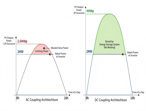 Hoe selecteer je gelijkstroomkoppeling en wisselstroomkoppeling in een zonne-energieopslagsysteem?
Feb 06, 2026
Hoe selecteer je gelijkstroomkoppeling en wisselstroomkoppeling in een zonne-energieopslagsysteem?
Feb 06, 2026
 Anti-eilandbeveiliging in zonne-PV-systemen
May 12, 2025
Anti-eilandbeveiliging in zonne-PV-systemen
May 12, 2025
 Hoe u het juiste zonne-PV-systeem kiest: residentieel versus commercieel
Jan 16, 2025
Hoe u het juiste zonne-PV-systeem kiest: residentieel versus commercieel
Jan 16, 2025
 Oplossingen voor lage isolatie -impedantie voor "PV -isolatie -impedantie is te laag"
Jan 02, 2025
Oplossingen voor lage isolatie -impedantie voor "PV -isolatie -impedantie is te laag"
Jan 02, 2025